Tools Required: 1.5mm and 2.5mm Hex Allen wrenches.
Left, right, front, and rear described in these instructions are from the operators perspective with the weapon held in firing position.
Clear the weapon. Then set Fire Mode Lever (Safety Lever) to the Safe position.
Remove the Trigger Housing. Place the palm of your hand on the Hammer to prevent it from swinging into the Extractor under spring tension when released. Turn Fire Mode Lever (Safety Lever) to fire and release the hammer by pulling the Trigger.
Remove the Case Securing Screw (button head cap screw above the Trigger). Note: if the screw can not be easily removed your Scorpion has a welded Trigger Case screw. The screw threads are welded to the insert in the Trigger Case. The head of the screw will be need to drilled out in order to remove the Trigger Case from the Trigger Unit Casing.
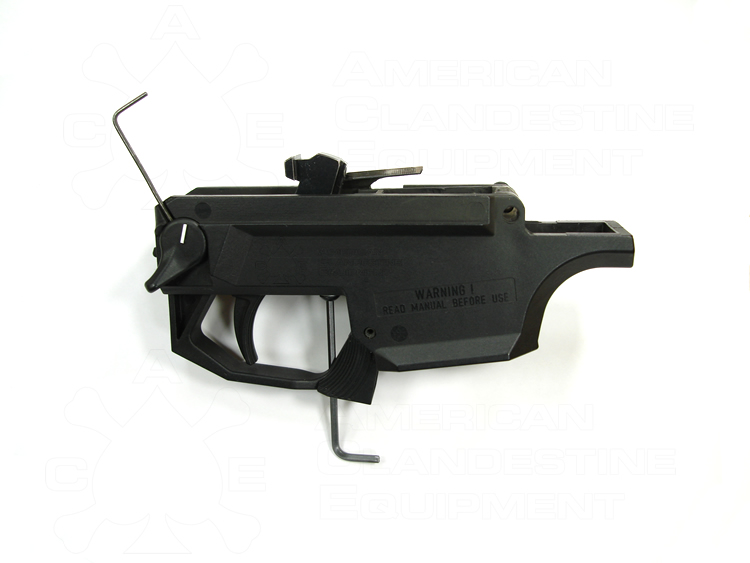
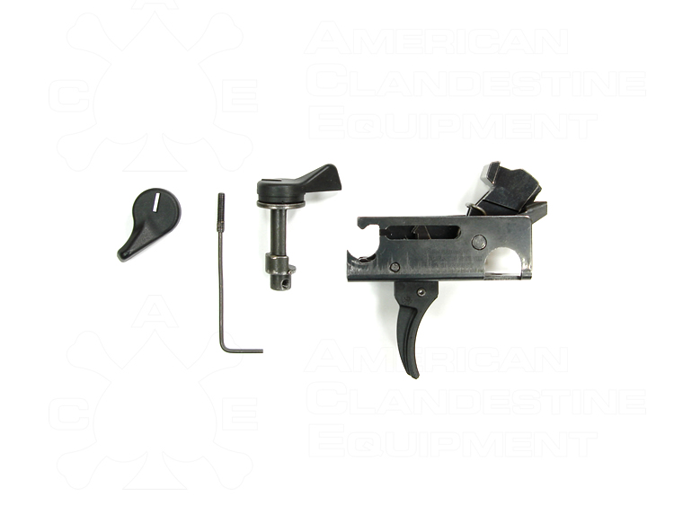
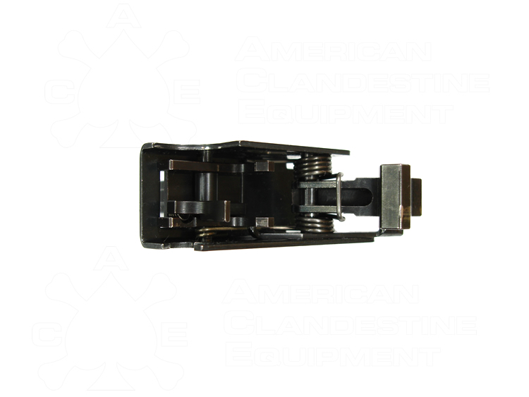
Remove the Control Screw from the right side Fire Mode Lever (Safety Lever) with the 1.5mm allen wrench. Remove the Ratchet Plug (Safety Plug) by sliding out the left side. Lift the Trigger Case out of the Trigger Housing. See Image #1 and #2 above.
Using the 2.5mm allen wrench remove the Hammer Pin by pushing the pin from the left side through the right side. When doing so place your index finger on the Block Lever to the rear of the Hammer Spring retaining it. The Block Lever is under spring pressure and will be rapidly dislodged when the Hammer Spring is removed. Remove the Hammer and Hammer Spring then the Block Lever.
The Trigger Pin retains the Trigger Spring through the center of the spring on the right side of the Trigger Housing.
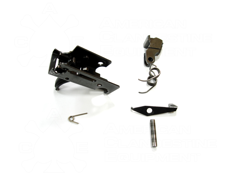
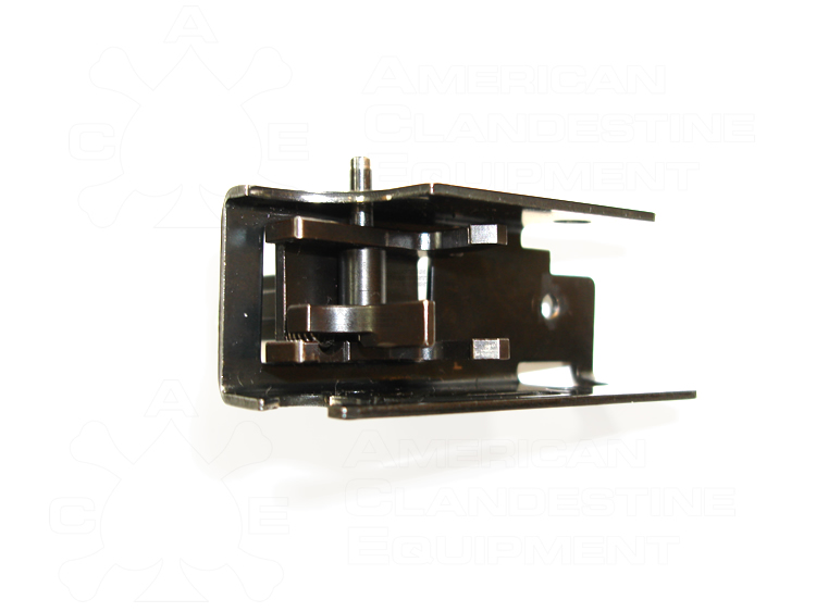
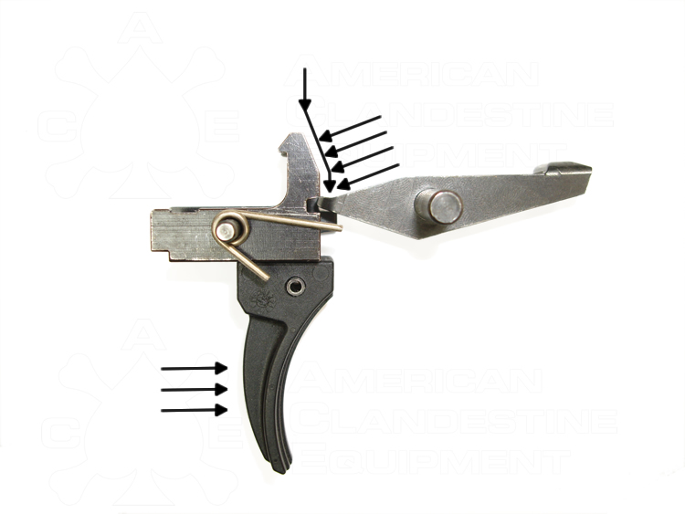
Using the 1.5mm allen wrench push the Trigger Pin from the right side to the left so that is flush to the Trigger Housing. The left side of the pin will protrude .18" (4.5mm) from the left side of the Trigger Case. There is no need to fully remove the Trigger Pin, enough clearance to remove the Trigger Spring is all that is required. Note that applying pressure to the top of the Disconnector allows the pin to slide more freely. Remove the stock Trigger Spring and replace it with the 5.5LB Spring. The short arm of the spring is oriented towards the bottom of the Trigger Case and both arms point to the front of the Trigger Case. Push the Trigger Pin back into operating position. See Images #2, #3, and #4 above.
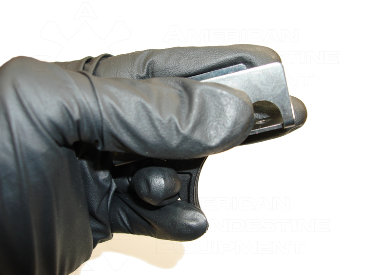
Hold the Trigger Case in the right hand as shown in image #5. Note that the ring finger is pushing the Trigger forward. If the Trigger is not held fully forward the Trigger Spring will not protrude far enough from the Trigger Housing to be contacted by the rear of Block Lever.
Slide rear of Block Lever down face of Trigger Housing maintaining pressure as indicated in Image #6. Keep the Trigger pushed fully forward. The rear of the Block Lever will be retained by the slot in the Trigger Housing with the 5.5LB Trigger Spring retained under the Block lever. Align the Block Lever hole with the Hammer Pin hole in the Trigger Case and insert the Hammer Pin just enough to secure the Block lever. Install the Hammer Spring then the Hammer. Be sure that the Hammer Spring ends are contacting the floor of the Trigger Case. Push the Hammer Pin into operating position. Test the trigger assembly for function.
Replace remaining components is reverse order of disassembly. Fully test for function including the Fire Mode Lever (Safety Lever).